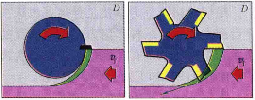
Climb milling refers to a machining method in which the movement direction of the tool teeth is the same as the tool feed direction when the tool rotates, as shown in Figure A.
During climb milling, the cutting thickness (green area in Figure A) is maximum when the tool tip starts to contact the workpiece, and is minimum when the tool tip is out of contact with the workpiece. The tip of the knife is less likely to slip when cutting from a thicker position. The cutting force component of climb milling points to the machine tool table (as shown in Figure A, pointed to by the oblique arrow at the bottom of the right picture).

The machined surface quality of climb milling is good, the back wear is small, and the machine tool runs relatively smoothly, so it is especially suitable for use under better cutting conditions and when processing high-alloy steel.
Climb milling is not suitable for processing workpieces with hard surface layers (such as casting surface layers), because then the cutting edge must enter the cutting area from the outside through the hardened surface layer of the workpiece, which is prone to strong wear.
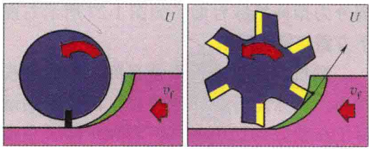
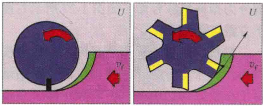
Conventional milling refers to a processing method in which the movement direction of the tool teeth is opposite to the tool feed direction when the tool rotates, as shown in B. In conventional milling, the cutting thickness starts from 0 and reaches the maximum value when the tool tip leaves the workpiece. The initial cutting thickness of the tool tip is 0, and the tool tip is often not absolutely sharp. Therefore, the tool tip is often in a slipping state during the short period of contact with the workpiece, although this slipping state is sometimes used to cause damage to the workpiece surface. Polishing, but this polishing effect often depends on processing experience. Different tools, different workpieces and different processing parameters, the results of these polishing effects will be different.

The slipping phenomenon that often occurs in conventional milling will accelerate the wear of the back of the tool, reduce the life of the blade, and often make the surface quality unsatisfactory (with widespread traces of vibration), and will also lead to hardening of the machined surface. The cutting force component during conventional milling is The force that causes the workpiece to leave the machine tool work surface is often in the opposite direction to the clamping force of the fixture. It may cause the workpiece to slightly separate from the positioning surface, making the workpiece processing unstable.
Therefore, conventional milling is rarely used. If the conventional milling method must be used for processing, the workpiece must be completely clamped, otherwise there is a risk of coming out of the fixture.
Figure C is an example of face milling. In this example, since the milling width exceeds the radius of the milling cutter, the milling is a hybrid application of climb milling and conventional milling. In the processed plane, the green part in the picture is the climb milling part, and the purple part is the conventional milling part. In conventional milling/conventional milling hybrid applications, the climb milling part should usually account for the major share.


